1. INTRODUCTION - FRONT S-CHASSIS SUSPENSION
The Nissan S-chassis front suspension is of MacPherson strut-type with a good design. As these cars are almost always lowered for more performance due to reduced height for the centre of gravity or just wheel fitment and appearance, the suspension geometry takes a severe change for the worse.
Problems such as bump steer and negative roll centre values are the most dominant. Bump steer causes twitchy handling due to constant change in toe alignment with suspension heave (travel) and negative roll centre values lead to vague handling and increase roll. Stiffer springs can be used for compensating negative roll centre height at the expense of mechanical grip, but the weight transfer response is still slow.
There are products such as bump steer correcting outer tie rods and roll centre correcting tall ball joints on the market. The problem with adjusting bump steer with only the outer tie rods is that the tie rod mounting on the steering knuckle is under an angle and for every mm of bump steer that is corrected the Ackermann geometry is also changed. The lower the tie rod pivot point is mounted the more Ackermann the steering linkage gains.
Roll centre correcting tall ball joints decrease clearance between the lower control arm and brake disc. It also changes Ackermann geometry and adds more bump steer if it is not adjusted for with the outer tie rod height, which would add even more Ackermann.
There are also good solutions on the market such as adapters that connect both the lower control arm and outer tie rod and lower them by an equal amount. The problem with those products is that they increase the scrub radius, making the steering heavier and increasing tyre wear on the outside of the tyre.
While the best idea might seem to run the car at OEM ride height, the lowered centre of gravity does have its advantages and geometric problems can best overcome with drop knuckles.
2. NEW PRODUCT – DROP KNUCKLES
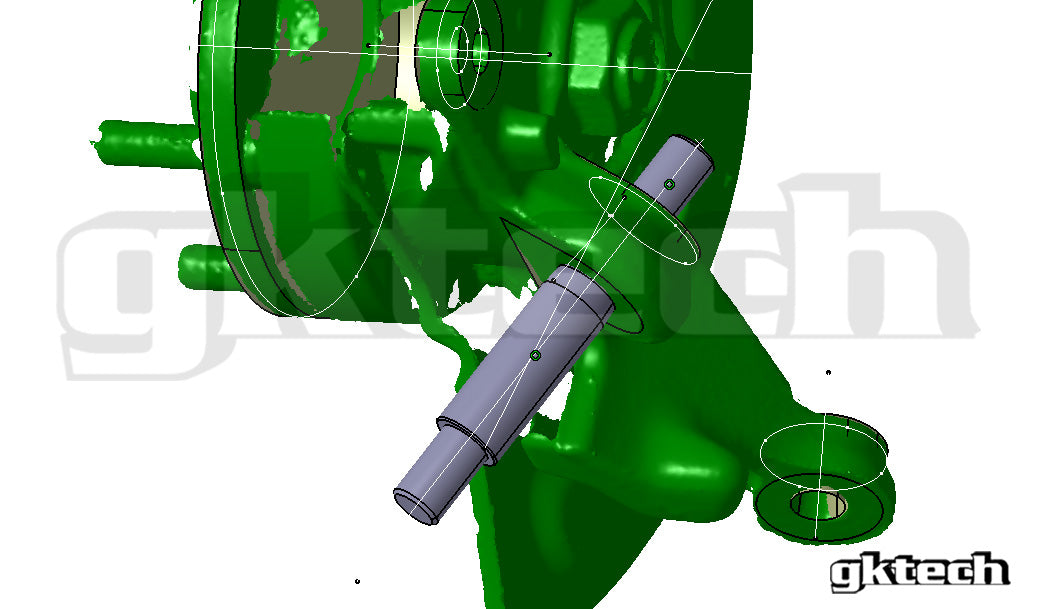
In order to proceed with the project it was important to measure the geometry of the OEM steering knuckles. The geometry was measured using a 3D scanner after which it could be imported into CAD software. Some of the parameters were also measured by hand using a digital caliper as the tolerances for machining could be figured out. Threads at the end of the bearing spindles also had to be checked with a thread comb.
The position of a lowered suspension also had to be accounted for to figure out how much roll centre correction should be provided. This was done with a simple tape measure and using a pointy weight at the end of a string mounted to the centre of a suspension pivot point. Since the MacPherson strut is one of the most basic types of suspension there are only a few points that needed to be measured on the chassis.
They were the pivot points of the inner tie rod, the strut and the lower control arm. These points were projected to the ground and coordinates obtained with a tape measure. This method is relatively simple but time-consuming for accurate results.

3. GEOMETRY ANALYSIS
After the necessary coordinates were obtained the data was input into 3D suspension modeling software and a virtual suspension model created. This would provide accurate information on the current geometry and kinematics of the suspension and all of the data can be exported to be plotted into charts using spreadsheet software.
It is important to analyze the current situation before starting to move the upright coordinates as they are all dependent of each other. Improving one parameter will usually have an effect on other parameters. Using computer modeling removes a lot of guesswork from designing good suspension geometry.
There is still the question of what tyres are used. Modern high performance street tire characteristics were taken into account when considering what the geometry should be like most of the customers would be using those since the product is mainly intended for track use.
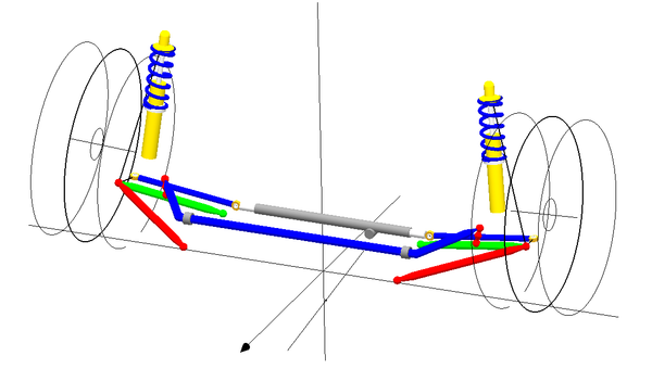
As the MacPherson strut is a basic type of suspension, not many changes can be done via redesigning the steering knuckle. The following parameters were the top criteria for a new GKtech drop knuckles:
- Roll centre height
- Camber gain
- Bump steer
- Steering angle and Ackermann geometry
- Steering axis inclination
- Mechanical trail
- Scrub radius
3.1 ROLL CENTRE HEIGHT
The roll centre height is an important parameter for a car’s handling. Its location dictates the amount of geometric roll resistance, geometric weight transfer, the speed of weight transfer and how quickly lateral force is applied to the tyres. It also effects weight transfer balance between front and rear axles (RC height is usually different on either axle). Since geometric weight transfer acts directly on the tyres and does not compress the springs, dampers and anti-roll bars (elastic weight transfer) then its response is much faster than elastic weight transfer (elastic suspension components) and reason for keeping roll-centre height above ground level.
This has a profound effect on the handling of the car. The higher the roll centre height the faster the weight transfer. If the roll-centre height is too high, the jacking (raising the body – lifting height of the centre of gravity – increasing body roll) forces are also higher. It does have the benefit of being able to use softer springs for better mechanical grip. If the roll-centre height is too low, for example below ground level then the geometric roll resistance is negative. This instead increases body roll as the geometric roll resistance value is negative. It is caused by lateral force generating a moment about the instant centre.
The height of the roll centre must be compromised between jacking, geometric roll-resistance and camber change in case of MacPherson strut. Spring rates must be accounted for along with steady-state cornering weight transfer. The static roll centre height was found to be -161mm, which is too low and even negative. This means there is no geometric roll resistance and the handling will be vague and unresponsive. It must be raised to be above ground level.

3.2 CAMBER GAIN
Camber gain is the gain in negative wheel camber during suspension compression and is considered a negative effect when the car is traveling straight and a positive effect when the car is cornering. This is because the increase in negative camber reduces the area of the tire’s contact patch with the road during accelerating and braking, but during cornering it increases the size of the contact patch. In the case of independent suspension the wheels roll together with the body of the car in the same direction and without camber gain the camber angle would be positive on the outside wheel (towards direction of roll).
This principle does not apply to strut based suspension types as the top pivot point is fixed to the chassis and is the major disadvantage of MacPherson strut suspension. This can be compensated for with high caster angles as during cornering the wheels are always steered and caster increases negative camber on the outside wheel and positive camber on the inside wheel. The downside to this compensation is that the body can be moving vertically but wheels stay steered in the same direction.
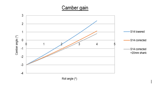
Ideally there would be no camber change during heave and a one to one ratio during roll but as that is not possible without complicated linkages if even then, a compromise is to be found. With MacPherson strut the suspension’s least camber change occurs if the lower control arm is parallel to the ground with its pivot points. The angle of the physical body is not relevant. With the current setup the -3° of camber changes to 2,3° with 4 degrees of body roll. This must be improved upon.

3.3 BUMP STEER
Bump steer is the change of the toe alignment during suspension heave and should always be minimized when designing suspension for use in high performance cars. Ideally it should not exist at all. Mass production cars often have bump steer by design to increase stability under braking (some do this with asymmetric rubber bushings) or to discourage drivers from driving at high speeds on the public roads. It is caused by suspension arms pivoting at offset axis from one another. The most critical parameter when tuning bump steer out of the suspension is the height of the pivot points in relation to each other and other suspension pivot points. Ideally they move in concentric arcs.
As bump steer tuning is required for the new drop knuckles it is important to place the outer tie rod bore vertically so it is perpendicular to the bearing spindle. This means the Ackermann geometry will be minimally affected by vertically adjusting the height of the outer tie rod pivot point.


3.4 STEERING ANGLE AND ACKERMANN GEOMETRY
Steering angle is one of the main reasons for the design of a new steering knuckle. While it is easy to get more steering angle out of an OEM steering knuckle via rack spacers it will be limited to the amount of teeth on the steering rack and the Ackermann geometry will not be changed.
Ackermann geometry enables wheels to turn at different angles with the same travel of the steering rack on both sides of the car. This is made possible by angling the steering arm inwards in relationship the horizontal axis of the car (vertical in Ackermann geometry figure). 100% Ackermann means that the imaginary extended lines from the bottom ball joint and outer tie rod intersect at the centre of the rear axle. Negative values mean that imaginary lines intersect ahead of the front axle.
Ackermann geometry is necessary as the radius of a corner is smaller for the wheel that is closer to the apex and larger for the wheel that is further from the apex. Parallel steering and anti-Ackermann geometries cause tyre slip at high angles when cornering if the tyre does not have enough slip angle. This doesn’t apply to drifting where the wheels are steered in the opposite direction and parallel and low values of anti-Ackermann steering can work well if the feedback is suitable for the driver.

Figure 7. Ackermann geometry defining factor shown in light blue
3.5 STEERING AXIS INCLINATION
Steering axis or kingpin axis (from kingpin steering systems of old) is the imaginary axis between the top and bottom ball joints of the wheel side suspension around which the wheels are steered. Its angle is measured between vertical line from the centre of the tyre and the steering axis.
Steering axis inclination (SAI) has effect on the car’s handling and performance when the wheels are steered. In static position it only determines scrub radius. Low steering axis angles are desirable as SAI removes negative camber from steered wheels that is added by caster angle. It is always a compromise between camber change and scrub radius.
Passenger cars are generally optimized towards low scrub radius for more comfortable handling and racing cars always towards performance. SAI can be reduced by moving the top pivot point of the strut outwards and camber compensated from the steering knuckle to strut mounting.

Figure 8. Steering axis inclination
3.6 MECHANICAL TRAIL
Trail is one of the main parameters to determine steering return rate along with caster and steering axis inclination. It assists in straight line stability and steering return rate. The value in the OEM steering knuckle is sufficient with suggested alignment for 7° of positive caster and provides enough return rate for the steering system.
When introducing drop to a MacPherson strut knuckle it should be noted to maintain the trail as directly moving the ball joint pivot point down reduces knuckle trail.
GKtech front steering drop knuckles for S-chassis will be developed as two distinct versions. The grip knuckle will maintain OEM parameters apart from roll centre and bump steer corrections and the drift knuckle will feature increased spindle offset to reduce the amount of caster required for same amount of trail for a more flat contact patch at lock.
This is beneficial only in drifting as it reduces weight jacking and bump steer at high steering angles. The wheels no longer tilt as much and bump steer is improved because the height of the outer tie rod pivot point changes less in relationship to the chassis pivot point.
Racing setups benefit from high caster angle is it helps with camber control.

3.7 SCRUB RADIUS
Scrub radius is the distance between the centre line of the tire’s contact patch on the ground and steering axis inclination’s intersection point on the ground. Typically these are designed to be as low as possible with common passenger cars to maximize the life span of the front tyres as it produces rubbing between the tyre and road surface when steering.
Negative values are also commonly used (steering axis intersects on the outer side of the contact patch) to increase braking stability as the elastic bushings enable toe-in to occur. Large scrub radius values also make the car’s handling susceptible to road imperfections and increase steering effort. Some scrub radius has to be designed into the suspension geometry to force feedback from the tyres to the driver.
With MacPherson strut suspension the scrub radius is always in trade off with steering axis inclination. It is possible to get around this limitation by using a virtual lower A-arm that has two pivot points on the wheel side, but this solution is not suitable for high steering angles as the two suspension arms would bind with proper parameters.

Figure 10. Scrub radius shown in light blue at the tyre contact patch
4. ANALYSIS SUMMARY AND DESIGN GOALS
After analyzing the kinematics based on the measured geometry of a lowered S14 it was decided that a new steering knuckle would need to be developed to achieve best grip and handling. The following parameters required changing:
PRO drift knuckle:
- 65° of steering angle
- Adjustable Ackermann geometry
- Bump steer correction
- 50mm ball joint drop for roll centre correction
- Increased spindle offset (thus trail) to use less caster for same steering return rate
- Welded assembly with sheet metal and machined parts
- ABS sensor provision if possible
Grip/Drift knuckle:
- 60° of steering angle
- Compromised Ackermann geometry for drifting and racing
- Bump steer correction
- 50mm ball joint drop for roll centre correction
- OEM spindle offset and trail
- Welded assembly with sheet metal and machined parts
- ABS sensor provision
- Cooling duct provision
Grip knuckle:
- OEM steering geometry
- Bump steer correction
- 50mm ball joint drop for roll centre correction
- OEM spindle offset and trail
- Welded assembly with sheet metal and machined parts
- ABS sensor provision
- Cooling duct provision
5. NEW STEERING KNUCKLE GEOMETRY
5.1 ROLL CENTRE HEIGHT
As the original roll centre height was underground, it needed to be raised. The lower ball joint was lowered by 50mm on all steering knuckle versions and this helped raise static roll centre height from -161mm to -20mm. Additional 20mm extended ball joint shank was used to raise roll centre to 8mm. Clearance between lower control arm, wheels and brake rotor must be considered when using extended shanks.
The graph below illustrates how sensitive this type of suspension is to changes to ride height. 1mm of lowering the body roughly equates to about 3mm loss in roll centre height. 20mm of lowering would mean the roll centre is lowered by 60mm showing how important it is not to over lower the car. RC is lower in the front of the car because the centre of gravity (CoG) is also lower. The distance between the roll centre height and the CoG forms the roll couple.
The lateral load acts on the CoG and uses the roll couple as a lever to roll the body of the car. The longer the lever the less force is required to roll the car by the same amount. Too short roll couples make for unnatural handling and reduced feel, also can make the car unpredictable at high lateral loads. There is also a tendency to make the body ‘hop’.

5.2 CAMBER GAIN
Camber change was improved by lowering the ball joint that resulted in a longer front view swing axis around which the pivoting occurs. The location is not static and moves with suspension links that determine its location. Since the MacPherson strut has no upper arm the top line is drawn perpendicular to axis of the strut (not with steering axis) because it has to be parallel with the damper - direction of movement.
Total camber change was reduced by 1 degree during 4 degrees of roll and 2 degrees during 100mm suspension compression. This enhances cornering by having a larger tyre contact patch and same applies to braking as the camber does not go positive anymore. The handling will also be more consistent and lower static camber values can be used.

5.3 BUMP STEER
Bump steer has been reduced by changing the height of the outer tie rod’s pivot point on the knuckle. The PROdrift knuckle also has a relocated inner tie rod pivot point via the offset rack spacer that places it 34mm outward and 30mm forward. The grip knuckle is aligned to 7° of caster and the PROdrift knuckle to 4°. Caster directly affects bump steer because it rotates the knuckle and thus changing the height of the outer tie rod’s pivot point.
The original knuckle on a lowered car produced 2mm of toe out per 10mm of bump. This has been reduced to just 0,02mm and is not linear. It is a dramatic reduction and results in greatly improved steering control and overall predictability of the car while cornering and travelling straight.
5.4 STEERING ANGLE AND ACKERMANN GEOMETRY
Drift knuckles feature adjustable Ackermann geometry with a rotatable tie rod locating insert. A tapered washer from the top secures it in the position by clamping it down. The design goal for PRO drift knuckle was 65° with reduced Ackermann angle.
Offset rack spacers or relocating the steering rack position are necessary to avoiding steering bind and when correcting Ackermann geometry at high steering angles. They keep the steering curve more linear at the cost of reducing maximum steering angle. This was countered by incorporating more rack travel into their design.
The Ackermann geometry has been plotted to a chart in Figure 13. All drop knuckles use GKtech 30mm offset rack spacers that extend rack travel up to 19mm, except the OEM/Grip one that has only inner tie rod washers fitted to increase the travel. While all knuckles except OEM/Grip can achieve up to 65 degrees of leading wheel angle, only the PRO drift model can do it without binding occurring. +3mm represents offset from the centre of the tie rod boss on the knuckle towards the chassis and -3mm further from the chassis. Grip knuckles will feature OEM steering geometry with improved bump steer.

Figure 14. Ackermann curves of GKtech drop knuckles
5.5 STEERING AXIS INCLINATION
Steering axis inclination has not been changed deliberately but is a result of the raised roll centre height and reduced camber change. As the bottom ball joint is reduced in height (relation to centre of the wheel) the steering axis inclination also changes. The lower the height of the bottom ball joint, the lower the steering axis angle. It is a positive change from camber control perspective but it does add some scrub radius that should be considered before the design is confirmed.
The actual value can be adjusted on the car via strut mounting on the knuckle and the chassis. Camber plates can be used to reduce SAI further and camber added from knuckle to strut bolt connection, there should be at least 10mm of clearance between the tyre and the coil spring.

5.6 MECHANICAL TRAIL
The grip knuckled will maintain OEM trail and the V4 PROdrift knuckle will feature offset spindle. The spindle is offset to maintain the same amount of mechanical trail as the OEM knuckle with 7° of caster. Grip knuckle was also designed for 7° of caster. The caster angle is 4° for V4 PROdrift knuckle. The result of this modification is reduced camber change throughout the steering range and shown in figure 16. Static camber value was -3° for all knuckles.


5.7 SCRUB RADIUS
The scrub radius value increased slightly, but is the only compromise made. The static value increased by 12mm for Grip and PROdrift knuckles. Extended shanks that increase roll centre height being used increase scrub radius by additional 5mm.
Scrub radius can be compensated for by using higher offset wheels. The wheels used for suspension modeling had offset of +20mm. Suggested maximum scrub radius should not exceed 100mm. It is recommended to keep it within 20-40mm for street cars. Full track cars can use more. Passenger cars tend to have negative values to improve braking stability.

5.8 GEOMETRY OF THE STEERING KNUCKLE
In order to accurately design the new steering knuckle the 3D scan data was used. Other components such as ball joint, wheel hub, wheel bearing, brake caliper, brake rotor, strut, simplified lower arm and tie rod assembly were modeled. Z32 front brakes were used as it is a common upgrade for S13 and S14 chassis. It also has the least clearance from the front lower control arm due to the thickness of the rotor and its offset.
The geometry changes were mostly optimized using susprog3D and steering geometry was modeled in CAD as Susprog can’t compute high steering angle values exceeding 40-50° depending on configuration.

5.9 TYRE CLEARANCE FROM STRUT
Tyre clearance from the strut was not altered but ride height raised by 8mm as this helped in improving the strength of the knuckle at the strut mounting area.
Maximum backspacing is 150mm with 14° of steering axis inclination. 17x8,5+20 with 225/45R17 tyre was used for the render. The spring is of 2.5“ diameter that is a common size for S-Chassis coilovers. This will also depend on coilover bracket offset.
There should be a minimum of 10mm of clearance between the spring and the tyre as they are both elastic and none of the other suspension components including the chassis and wheel are not 100% rigid either.

6. WEIGHT REDUCTION
6.1 CALCULATIONS
In order to find forces that act on the suspension calculation module was built in spreadsheet format. Lateral, horizontal and vertical forces were calculated using input parameters such roll centre height, centre of gravity height, track width, wheelbase, spring and anti-roll bar rates, corner weights, unsprung mass in each corner plus tire unloaded radius and its spring rate. Reasonable accelerations were assumed such as 1G for braking and accelerating, 1,2G for cornering. These values will be later used in topology optimization.
The most critical loads for front steering knuckle occur during braking and steady state cornering. Impact forces also have to be accounted for as the knuckle must be the last part in the suspension to fail. Stiffness is also important as with low stiffness bearing spindle and brake caliper mounting brake caliper piston knock can occur during hard braking. Camber stiffness is also important.
The suspension arms are the easiest to replace and should be regarded the weak links in the suspension.

6.2 FINITE ELEMENT ANALYSES
A finite element analysis was used to optimize the weight and strength of the new GKtech steering drop knuckles. It has the benefit of showing where and how big the stresses in the material are. This information was used to improve the design by removing material from where it was not necessary and added to where the stresses were too high. It was important to remove any concentrated areas because the knuckle is dynamically loaded and that will cause the material to fatigue and welds to crack.
This stage was iterative as any changes to the design resulted in different material stress values, locations and evenness. Ideally the product should be equally stressed, but that was not possible due to manufacturing technology selected. It is also because there are different load cases that cause the stress flow to be different.
Steady state cornering at 1,2G lateral acceleration, hard braking at 1G horizontal acceleration and side impact scenarios were modeled and the product design updated accordingly to withstand normal use and impacts. Brake caliper mounts were optimized in the braking scenario and as there is no force applied to the brake caliper in steady state cornering the area is lowly stressed.

6.3 COMPONENT DESIGN
After the FEA results were satisfactory enough by having the maximum principal stress 4x below the yield strength of the materials chosen in each load case. The next stage was to divide the knuckle into specific components that are to be welded together.
When designing components a compromise must be found between complicated parts for manufacturing and for assembling. The fewer parts the easier it is to assemble, but with more parts there is no need for bending and simpler parts can be produced in an effort to keep the costs low. As the geometry of the steering knuckle requires high precision it was decided that more complex parts have an advantage over simple parts for speed, accuracy and ease of assembly.
The welding jig would also be simpler. More accurate parts increase the assembly speed in the welding jig as parts don’t need to be hand modified or held for a correct fit. All the manufacturing tolerances are incorporated into the design and parts will fit together and without excessive play. Thickness of the surface coating also has to be accounted for.
The bearing spindle, tie rod and ball joint bosses and strut mounting bosses are CNC machined from high strength steel. The offset spacers for the brake caliper mounts are lower grade steel but also produced on a CNC lathe. The sheet metal parts are CNC laser cut and formed on a CNC bending machine.

GKtech products follow the Japanese Kaizen philosophy to constantly improve products. Updates are mare as soon as faults are found or better solutions and designs envisioned. The main reasons for updates have been consistently adding steering angle while reducing Ackermann and simplification of the assembly procedure. As steering angle was added a lot to the trailing wheel the brake caliper had to be rotated higher for clearance that was previously lowered for lower CoG.
- Prototype version
- Improved parts for welding assembly, improved coilover clearance, increased brake caliper mounting bore
- Improved parts for brake caliper mounting area welding to allow post machining,
- Major Update - rotate brake caliper upwards to avoid problems with high steering angles (65° trailing wheel angle), new brake caliper mounting design to simplify design and reduce possibility of welding deformations, increased steering angle, reduced Ackermann geometry, reduce bore size inside bearing shafts by 2mm
- Updated welding jig, add a cap to the bore on the inside of the bearing spindle
- Reduce bore size inside the bearing shafts by 2mm, one piece brake caliper mount with spacers in the rear for correct bolt offset, improved welding of the brake caliper mount
- Add provision to bearing spindles for easier install of the wheel bearing
- Major update - prototype for adjustable Ackermann geometry – all new tie rod pivot point, redesign majority of the knuckle
- Production version with adjustable Ackermann geometry + Grip knuckle with OEM steering geometry + third option with V2 knuckle steering geometry to make a compromise between drifting and racing driving

7. TESTING
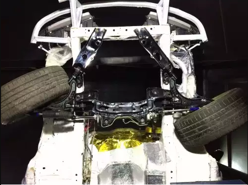
The front drop knuckles were originally tested on the GKtech S14. The car used R18 high grip tyres and went through several track tests doing autocross and drifting. As the steel knuckles are V2 version of the GKtech knuckles after the original V1 billet aluminum ones, there were few changes to the original geometry. The geometric results were known to be successful as they had been tested before so the testing stage for V2 knuckles primarily focused on strength. The knuckle passed these tests it was put into production.
8. SUMMARY
In conclusion all the design goals were achieved. As with all GKtech products it is a constantly improving product to help keep it on the market as long as possible and always be on par or surpass others in the market.
The changes made to the geometry of the new drop knuckle compared to the OEM one resulted in a greatly improved handling and better lap times.
The most important change was the raised roll centre height that fixed turn-in understeer and reduced camber change. The pivot point for the outer tie rod was relocated and the result was significantly reduced bump steer. This allowed better control over the car at the limit and improved driver confidence even during street driving as the car did not wander over bumps, pulling to either direction the car was slightly steered towards.
The PROdrift drop knuckles feature significantly enhanced steering angle and allows for very high steering angles to be reached without spinning the car. The adjustable Ackermann allows the drivers to fine tune their car to their needs without having to change knuckles. This can be at the track as the change of direction for the tie rod insert results in a 6mm change in toe that can be compensated by 4 full turns of the M14x1.5 inner tie rod. Lower caster angles can also be used with same amount steering return rate for less static camber to achieve full contact patch of the tyre. Having less static camber also improves braking performance.
Author: Siim Õisma
Bsc Automotive engineering, Msc (in training) Product development
GKtech engineer since 2013
USA store product link - https://us.gktech.com/240sx-front-drop-knuckles
AUS store product link - https://au.gktech.com/s-chassis-front-drop-knuckles
JPN store product link - https://jp.gktech.com/v4-super-lock-s-chassis-pro-front-drop-knuckles

