The R chassis is a very popular platform in circuit racing with the GT-R models, but so are the 2WD versions in drifting. But only in countries such as Japan, Australia, New Zealand, The United Kingdom and other left hand traffic countries. As such, they have not received extended aftermarket support for modifications in regard to suspension and steering as a complete package, only adjustable arms. The front suspension is also rather complicated compared to a MacPherson strut and owners have been limited to modified OEM knuckles.

Figure 1. R33 Skyline front suspension assembly
1. KNOWN R CHASSIS FRONT SUSPENSION ISSUES
The R chassis features a relatively advanced design for its time but is full of strange issues. It appears to have been designed for very fast camber gain but disregarded many other aspects of suspension design.
The early model R32 chassis is known for having the worst front suspension geometry of the R32 through R34 generations. The Z32 chassis also shares a similar geometry with R32 but has been improved over the R32.
The problems are very fast camber gain, high anti-dive value, lots of tyre scrub during track width change, lots of chassis jacking and torque steer on high powered cars.
Many of these problems are caused by a high angle mounted very short length upper control arm. It is also positioned on a strange angle, most likely for packaging reasons. This was replaced on R33 and R34 models with a much better placed and designed A-arm.
The front suspension on the R32 also binds the upper control arm knuckle side bushings as the knuckle rotates backwards when the suspension is compressed

Figure 2. R32 front suspension assembly
2. SUSPENSION GEOMETRY
2.1 FRONT VIEW INSTANT CENTER
As the front view instant center (FVIC) is located high off the ground there is a lot of tyre scrub. This means that the track width changes a lot during suspension travel and this disturbs the balance of the tyres in a corner. This effect is strongly pronounced on uneven and rough roads.
High instant center also means high roll center height from ground. This could be simple to fix with lowering the ride height but that also quickens the camber curve as the front view instant center is now shorter. Camber gain is dictated by the length of the front view swing axis and nothing else. The good side of high roll center height is that it provides roll stiffness without using stiff springs and mechanical grip can be improved with softer springs. The downside is that it causes excessive jacking as lateral force from the tyre generates a momentum about the instant center point pushing the wheel down to the ground and lifting the sprung mass, which is the body of the car. The higher the instant center point is off the ground, the more momentum is generated to lift the car.
It is important to keep the roll center height above the ground as it also helps with handling. This is because positive roll center height contributes to geometric weight transfer that only includes the tyres. Elastic weight transfer first has to compress the springs, dampers, chassis and anti-roll bars so with positive roll center the handling will be sharper and faster. It also affects front to rear chassis balance due to the roll axis formation.
Figure 3. R32 Front suspension Roll center and front view swing arm-post optimization
2.2 SIDE VIEW INSTANT CENTER
The side view instant center is also very high off the ground resulting in a high anti-dive value. Anti-dive reduces pitch during braking so softer springs could be used for better mechanical grip. The values should be kept minimal as on rough roads the wheels may lock up easily as the suspension cannot be compressed as easily since anti-lift resists it.
Anti-dive is defined by the SVSA angle relative to the ground and SVIC distance from center of the front axle and height from ground. Changing the height of the tension rod chassis side pickup point is the most effective way of tuning the value.

Figure 4. R32 Front suspension side view instant center and swing arm-post optimization
3. SOLUTION
With multilink suspension designs it is often not possible to fix the issues of lowering the ride height with simple bolt on mods such as extended ball joint shanks or spacing the ball joint down on knuckle like for example the GKtech S chassis RC kit.
This is also the case with R chassis front suspension. RC kit would cause excessive jacking of the suspension and bring about a very short front view swing arm that will make the camber gain very fast.
The maximum steering angle can also only be increased with steering rack spacers and if even more lock is required then the knuckle has to be modified.
Taking into account all these restrictions it was decided to make a brand new fabricated front steering knuckle.
The design requirements for the new knuckle were the following:
- Raise the roll center for more roll resistance and improved handling
- Decrease camber gain for more even tyre wear
- Reduce bump steer for better handling
- Increase maximum steering angle
- Reduce weight of the steering knuckle for less unsprung mass
- Use S-chassis wheel hubs
- Must be able to use 18” wheels with 235/40 tyres
3.1 NEW SUSPENSION GEOMETRY
The OEM steering knuckle was 3D scanned to obtain accurate geometry for modeling and analysis. This allows us to accurately locate all the mounting and pivot points.
The kingpin shaft was lowered closer to the centerline of the axle and lower ball joint dropped even further. This helped to create a slower camber gain by extending the front view swing arm and optimize the roll center height.
As the steering axis is determined by the kingpin/third link bearings, it was also crucial to make sure the new geometry did not have the bottom ball joint pivot point out of line from the steering axis. An offset ball joint causes suspension bushing wear due to forcing the lower arm to rotate forwards and backwards. This situation is much worse in cars with all spherical bearings as an offset ball joint will cause excessive suspension jacking (lifting outside wheel, lowering inside).
Anti-dive value unfortunately cannot be fixed much with the knuckle and should be done on the chassis side by raising the height of the tension rod mounting hole from relative to the ground.

Figure 5. 3D scan with GKtech lower control arm ball joint shank
3.2 NEW STEERING GEOMETRY
As most GKtech customers are drifters the steering geometry was revised for increasd maximum steering angle and reduced Ackermann angle at lock. Bump steer was also reduced by lowering the tie rod mounting boss.
The geometry is designed to be used with 30 mm offset rack spacers for correct Ackermann geometry and bind free operation. The maximum steering angle is 65-60 degrees depending on chassis installed on (R33 has least steering rack travel of the R32…R34 generations).
The values presented for steering angle are using OEM rack stroke of 68.5mm. More steering angle can be achieved without offset rack spacer, but there is a high risk of tie rod becoming parallel with the steering arm on the knuckle and steering bind occurring.
 Figure 6. new Steering geometry
3.3 NEW KNUCKLE DESIGN
At first it was decided to use S chassis wheel hubs as R chassis bearing housings are large in size and assumed heavy. The first design also featured fabricated sheet metal brake caliper mounting which was reinforced in the rear side with U shaped sheet metal pieces. The design also featured machined bearing spindle shaft, kingpin shaft, brake caliper bosses, tie rod boss and bottom ball joint boss. There were four sheet metal pieces in total which kept the number of parts to a minimum
Figure 7. first design for new knuckle
3.4 FIRST TEST FIT
The first version was 3D printed from ABS plastic and test fitted on an R32. The spring was removed from the coilover to check the geometry throughout the range of the suspension travel.
The steering geometry was also checked for lock and binding but unfortunately the steering arm broke during the process as the tie rods were new and tight and had enough resistance while steering turning to break the mounting boss off the plastic steering knuckle.
The brake system was also test fitted to check clearance, but not pictured as it would hide the knuckle itself. Figure 8. 3D printed ABS plastic prototype test fitting
3.5 FIRST PROTOTYPE
The first prototypes were built after the test fitting was successful. They were assembled on a jig and then TIG welded together. TIG welding is slow for mass production, but is our preference because it provides better weld penetration than MIG/MAG welding.
 Figure 9. Welding jig
 Figure 10. First produced R chassis steering knuckles
3.6 FIRST TESTING
The testing of the new knuckles was a success. The steering angle and geometry was as designed and was a significant improvement over OEM for drifting. The geometry still maintains positive Ackermann angle geometry at lock so they can also be used for circuit racing if 2WD Skyline is vehicle of choice.
There were a few problems discovered during the testing process. As the goal of the design was to make the upright as lightweight as possible, the spindle shafts were hollow inside. The kingpin one unfortunately was not strong enough and must be updated for the next version.
 Figure 11. Maximum steering angle on R32
 Figure 12. Kingpin shaft strength issue
3.7 SECOND DESIGN UPDATE
The second update of the knuckle went through a major redesign. The S-chassis wheel bearing idea was abandoned, and OEM wheel bearing was used instead to reduce end cost for the customer. It required a redesign of all components.
The kingpin shaft was reinforced using smaller inside diameter. As the shaft was made stiffer there was also more stress at the base of the shaft. The shaft could not be strengthened with a tall chamfer, so stress relief grooves had to be cut into the base. This reduced stress as the base by 30% and is shown in figure 13, nr. 1. The second stress relief groove is also present in the OEM knuckle and allows the bearing to be seated on the base without a chamfer and not compromising strength as much as without it. The transition from the spindle large diameter to small area was also redesigned to be as smooth as possible for stress distribution.

Figure 13. Original kingpin spindle vs. revised design
The bearing housing had to be completely redesigned for the reason of going with the R chassis wheel bearing. The housing was FEA optimized for light weight and strength.
Brake caliper mount was replaced with a single piece sheet metal for easier assembly and less welding length. It was important to reduce the total welding length for less heat warping and heat affected zone that reduces strength of the base material. Washers were added to the inner side of the bracket and are welded to the knuckle to make sure the OEM brake caliper bolts can be used and their usage also allows for much wider range of caliper adapters.
Steering arm position was retained from the original design and new sheet metal pieces designed around it to make it work in the new assembly.
The difference in weight between the two designs it that the R chassis bearing version weighs 0,17kg more. In a fully dressed assembly the S chassis bearing version would even more lighter as the R chassis wheel hub is heavier. Generally speaking the press-in bearings provide better upright stiffness as the diameter of the bearing mount is significantly larger. In this case it is a 34 mm shaft (S14) compared to R chassis’ 76 mm.

Figure 14. Original design next to R chassis bearing version
3.8 SECOND PROTOTYPE AND TESTING
The second prototype was tested on a wider range of cars and the new design was less compromised than the first one. Installing the knuckles on an R34 chassis required brake caliper bolt holes to be drilled out from 12mm to 14mm. After passing numerous track tests the knuckle design was approved for production.

Figure 15. R34 GTS-T test fitment
3.9 PRODUCTION VERSION
The production version received an improved welding jig, thicker brake caliper tab sheet. The kingpin shaft bracing sheet metal pieces were also updated for more even stress distribution and thus strength. Changing the angle of the bending also allows for better weld penetration. As R34 chassis cars use M14 brake caliper bolts the mounting holes in the knuckles need to be drilled out to 14mm.

Figure 16. Welding jig and welded product
4. Z32 FITMENT
These knuckles are also compatible with Z32 chassis front suspension. We recommend using the GKtech upper control arm for fitting them as others may not work or will bind. As seen in the figure 17 the steering angle is increased substantially. Suspension geometry is also improved.
 Figure 17. R32 knuckles fitted to Z32
5. 4WD MODEL FITMENT
These knuckles are incompatible with the GT-R and other 4WD versions of the R32 through R34 chassis because the front suspension components are very different. While the 2WD versions have the kingpin shaft in the knuckle, the 4WD versions have it inside the third link/kingpin and it is a taper fit to the knuckle. The wheel bearings are different and so is the lower control arm mounting method. The 4WD models have the bottom ball joint pressed into the steering knuckle’s detachable block while 2WD models have it inside the lower control arm. The lower control arms are also not exchangeable between 4WD and 2WD models as the chassis mounting is different.
It may be possible to fit them to 4WD models, but that would require adding mounting tabs to the front subframe to use RWD lower control arm or a custom one built. RWD model kingpin must also be used. There is no information on how the driveshaft, bearing and wheel hub fit or differ between the models.
 Figure 18. R32 GT-R front suspension diagram from R32 GT-R FSM
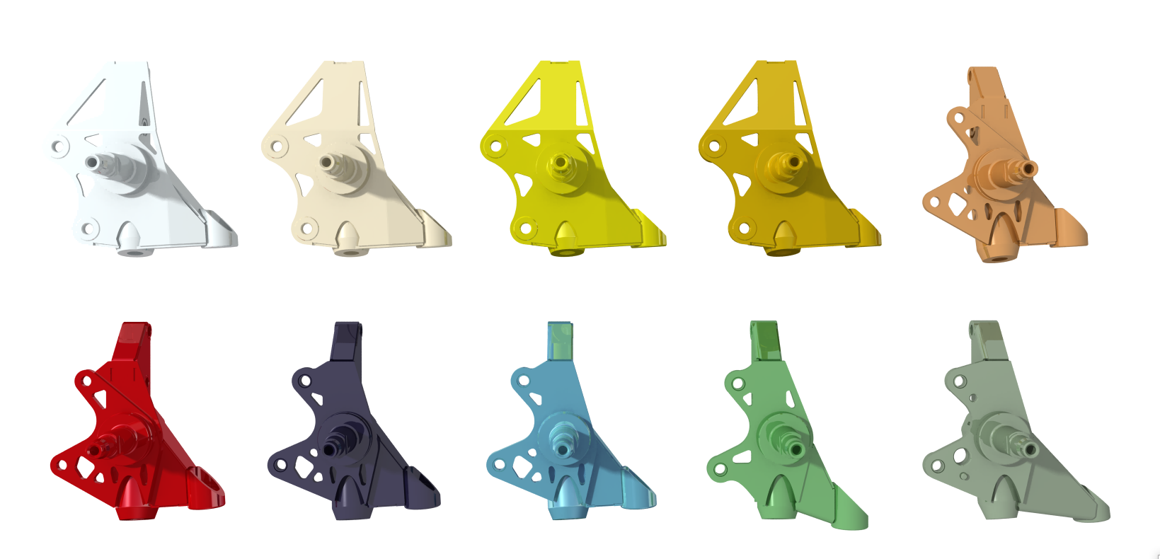
6. GKTECH R CHASSIS STEERING KNUCKLE FEATURES & BENEFITS
The production version of the GKtech R chassis steering knuckle has the following features and benefits:
- 1) Increased steering angle 60-65° depending on steering rack and supporting mods
- 2) Reduced bump steer
- 3) Reduced camber gain for more even tyre wear and more grip
- 4) Raised roll center height for more roll resistance
- 5) Reduced jacking for faster cornering
- 6) Reduced tyre scrub for better grip and handling
- 7) Reduced weight by 2,8kg in total for less unsprung mass to help wheels follow the road better
- 8) Based on 3D scanned OEM knuckle
- 9) CAD designed for accuracy and FEA optimized for strength and weight
- 10) Uses OEM wheel bearing
- 11) All components from high strength CrMo steel
- 12) CNC machined parts for easy fitting
- 13) TIG welded for strength, weight and appearance
- 14) Zinc coated for longevity
- 15) Wheel speed sensors are not supported
7. CONCLUSION
In conclusion the product has been a success. Decision to use the OEM wheel bearing has so far been valued approach as it is the only one on the market to feature it. Another success is the fact that they can be fitted to the Z32 chassis. The geometrical improvements make the front suspension handle significantly better than it could be with extended ball joints and other pieces to correct roll center while compromising other parameters. We recommend raising the tension rod chassis side mounting if possible to improve braking performance by lowering anti-dive value. Upper control arm should be as long as possible with required wheel fitment. We recommend using longer lower arms also. It further reduces problems of the suspension design. New wheel bearings should be used as old are difficult to remove intact and are most likely worn out due to the age of the cars.
The reduced Ackermann angle and shorter steering arm are also beneficial for circuit racing cars as they provide faster and more responsive steering with better slip angles. They will however scrub at higher steering angles when the car is not used for drifting.
There was also a significant amount of unsprung mass reduced on the front axle, totaling at 2,8 kg per two knuckles. The weight of the R and Z chassis front suspension has always been an issue and now with lighter components the dampers don’t have to work as hard to reduce bump inertia and wheels can follow the curvature of the road more closely.
Figure 19. R32 front suspension assembly
USA store product link - https://us.gktech.com/r-chassis-r32-r33-r34-front-super-lock-knuckles
AUS store product link - https://au.gktech.com/products/v2-super-lock-r32-r33-r34-z32-front-knuckles
JPN store product link - https://jp.gktech.com/v2-skyline-r32-r33-r34-z32