FRONT LOWER CONTROL ARMS

1. INTRODUCTION
The Nissan S-chassis front OEM lower control arms consists of a transverse link and a tension rod. The transverse link is loaded during cornering with some load applied to the tension rod and under braking the tension rod is loaded under massive tension. This is also the link in the front suspension that gets replaced or upgraded as soon as stiffer aftermarket suspension is fitted as the large silicone filled bushing deflects a lot under braking. It is made compliant from the factory to reduce road noise and vibrations. It also increases stability under braking by allowing enough deflection to increase toe in.
The reason it is replaced as often as it is, is because with stiff springs and high grip tyres the deflection is too great and results in low driver confidence and unpredictable handling. It is commonly upgraded with polyurethane bushings. There are adjustable length tension rods for caster adjustment that feature spherical bearings for play free operation without binding. If polyurethane bushings are used in OEM tension rods they must feature tapered design for the steel insert as the arm is under an angle and will otherwise bind.
As these parts are simple straight rods they are a limiting factor in achieving maximum steering angle clearance for both of the front wheels and limit maximum wheel and tyre sizes. There are a few good solutions available on the market such as complete front suspension kits that are costly and do not allow step-by-step upgrading as the parts don’t work with OEM steering knuckles. High clearance tension rods combined with OEM transverse links are not as strong or as stiff as single piece lower control arms due to slip between bolted components.
2. NEW PRODUCT – FRONT LOWER CONTROL ARMS
While a clearance increasing tension rod with offset rod end spacers and non-adjustable transverse links (lower control arms) were already on sale, it was decided to develop a single piece design lower arm to combine their properties while adding more features and improved wheel clearance.
It was important to study the OEM lower control arms assembly properties and its geometry in an assembled state in order to proceed with the project. The geometry was measured using a coordinate measuring machine. Both S13 and S14 versions were measured as they could be different. They differ from one another in length. S14 has 20 mm longer tension rod and 6 mm longer transverse link. These measurements are taken between pivot point and bolt hole centers. A 3D model was created for more convenient reference data. The tapered angles of the ball joints were also CMM measured as they also differ between S13 and S14. Other dimensions were taken with a digital caliper.

Figure 1. S13 front lower control arms assembly’s measured geometry
3. DESIGN PROCESS
Next step was to set design goals for the new product. The design goals were the following:
- Single piece bodied A-arm
- 65° wheel clearance for leading (tie rod clearance) and trailing wheel (rim and tyre clearance)
- Track width adjustability
- Caster adjustability
- Adjustable steering angle limiter (lock stop)
- Ease of adjustment
- Lightweight and durable design
- Anti-roll bar mounting provisions with adjustable motion ratio and track width extension compatibility
- Roll center correcting extended ball joint shank as an option
- Use of rod ends and spherical bearings
- Environment sealed bearings
- Combine S13 and S14 versions if possible
3.1 FRONT SUSPENSION CLEARANCE MODEL
In order to accurately design the body of the new lower control arms for wheel and tyre clearance it was important to model everything around it. As the geometry of the lower arms already provided coordinates for the chassis side suspension pivot points and having an existing model of the front steering knuckle it was possible to acquire the top pivot point through wheel alignment specifications, geometry of the strut (coilover) and the geometry of the steering knuckle.
There was also a pre-existing suspension model of the front suspension from the design process of the front steering knuckles. This was used to confirm the location of the strut’s pivot point as it can be adjusted with camber/caster adjustment top mounts and is not a fixed coordinate.

A 3D model was assembled after all the parts had been modeled in which the body of the lower a-arm could be designed. The wheel used for clearance considerations to the lower control arms was sized at 18x9+35 with a 225/40R18 tire. Another wheel and tire combination that was used for inner rim clearance was 17x8.5+20 rim with a 225/45R17 tire. The smaller wheel had to be modeled as the inner rim is smaller in diameter and could contact the lower arms.

After establishing the design constraints, it was time to model the body of the new high clearance A-arm. The wheel and tyre assembly was first adjusted parallel to the car and then rotated 65° as a trailing wheel on the steering / kingpin axis. This axis is an imaginary line drawn between two points. The top point is the pivot point of the strut. (spherical bearing in case of a camber / caster plate and the bottom point is the center of the ball joint bearing)


Pinch bolt clamping style was used on all GKtech suspension arms so it was also decided to use it on the new front lower control arms. This design resulted in too little space between the tyre and lower control arm assembly. Since tyres are elastic there has to be more clearance than the minimum requirement of a 65° trailing wheel.
The concept was abandoned in favor of a simpler and more compact jam nut locking design. 8 mm of extra clearance was gained by doing this. S13 fitment OEM length version lower arms was extended by 10 mm to make the tyre clear the chassis. The S14 standard version is the same length as OEM.

After redesigning the arms to use the jam nut there was enough clearance with the R17 tire on the S13 to utilize 65° of trailing wheel angle. R18 clearance is also good but the tire in the model is stretched (225/40 on 9” wide wheel). An extended version of the arms was also developed to increase clearance for cars with wider tyres or higher offset wheels. It was extended by 35mm. S14 version OEM length was retained for the shorter version as it was not necessary to increase its minimum length configuration and 35mm added to the extended version.

Leading wheel position was modeled with the steering wheel and tyre assembly 65° in the opposite direction. The assembly was then updated to bring the tie rod into alignment with all the other components in relation to the wheel and tyre assembly. This allowed for accurate modeling of the lower arms around the outer tie rod. Clearance was left for a lock stop to be added later. GKtech outer tie rod kit was used in the model.
Drifters often modify this area on OEM arms for more clearance as the straight design does not allow high steering angle on the leading wheel. This often can lead to weakened transverse link (lower control arm) if it is not reinforced properly. The curve should be as long and as smooth as possible.
The placement of the anti-roll bar mounting link was the main design constraint in this area as it takes up quite a lot of space that could otherwise be used for a smoother design.
Clearance for lock stop also had to be implemented, this would be produced from sheet metal and be adjustable for different knuckles to avoid binding the steering linkage. It was important to keep aftermarket and modified OEM steering knuckles supported.
3.2 SPHERICAL BEARING CLEARANCE
One of the major design problems was the clearance of the wheel side ball joint. QA1 high misalignment spherical bearing was used for maximum articulation, however, it did not have enough clearance at full lock. Even with the suspension arm parallel to the ground, as it's suggested to set ride height for sufficient roll center height. Roll center correcting 20 mm extended ball joint shank was used.

A bent type main body of the suspension arm was considered to increase clearance without having to machine the spherical bearing housing under an angle. This would have required increased material thickness and produced a much heavier part.
The problem with a bent arm is that bending should be done after machining and it is` difficult to form the part correctly without unwanted deformations. Second problem is that it is less stiff against lateral loads. A straight design should be pursued for best weight to strength ratio.

A solution was found in the form of splitting the arm into several components. A separate ball joint housing would be added to the arm through the process of welding. This did mean increased complexity as the provision for the housing would have to be machined under an angle from a front view and side view. The same applied to the welding jig.
The benefit of this design is the possibility to produce a relatively simple main body design with a good ball joint to bearing clearance and more articulation to cater for different wheel alignments. It also allowed sealing the spherical bearing with a rubber boot placed between the knuckle and lower arm.
A common wheel alignment of -3° camber and 7° caster was used for the design process.

4. CALCULATIONS
A calculation module was built in spreadsheet format in order to find forces that act on the suspension. Lateral, horizontal and vertical forces were calculated using input parameters such as roll centre height, centre of gravity height, track width, wheelbase, spring and anti-roll bar rates, corner weights, unsprung mass in each corner plus tire unloaded radius and its spring rate. Reasonable accelerations were assumed such as 1G for braking and accelerating, 1,2G for cornering. These values will be later used in topology optimization.
The most critical loads for front lower suspension arms occur during braking. Impact forces also have to be accounted for. The lower arm must be designed as the weak link in the suspension assembly if there is no upper arm that can be designed as the weak link as they are smaller and lighter already due to being mounted higher from the point where the forces act upon in relation to the lower arm. In the case of the MacPherson strut the strut itself acts as fixed upper arm should not be left as the weak link as they are expensive.
The suspension arms are the easiest and cheapest to replace. The arm would be made strong enough that small incidents would not damage it as it should not be considered as a consumable.

5. WEIGHT OPTIMIZATION
As the process of designing a high wheel and tyre clearance a-arm is a concurrent process between design for strength and design for clearance. Finite element method was used and material placement was optimized without sacrificing clearance. It was achieved through FEM showing highly stressed areas and then adding material to where it was possible and removing it where it was not. It was important to spread out the stress as evenly as possible due to clearance constraints.
The strongest and lightest design would be straight tube from tension rod pivot point to ball joint pivot point. Spreading the stress out over larger area reduces maximum values and helps to reduce material fatigue. High strength steel was chosen for the body of the a-arm for its high strength and ease of fabrication.
The downside of this material is the machining cost compared to aluminum as the process is slower, but as aluminum is brittle with low elongation before breaking, it was considered suitable. Aluminium is also more expensive per Kg and welding parts to it would not provide enough strength. Steel has a big advantage of yielding a lot before breaking so in case of an accident the car could still be moved on four wheels.
As the design for clearance compromised the design for strength, the only way to make the part strong enough was to increase the width and height of the arm. The standard length arms are 20mm thick and extended version is 24mm. The additional height for extended arm was the result of longer lever acting on the pivot points, resulting in increased material stress.
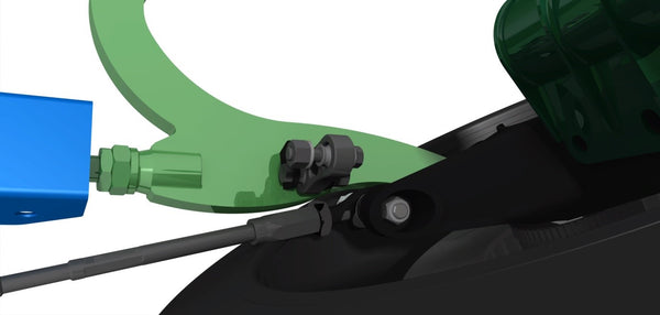
Anti-roll bar mounting features three holes to keep its position correct in relation to the chassis. The location of the anti-roll bar end link can be repositioned to any of the three adjustment holes. This also changes the roll stiffness by changing the motion ratio between the wheel and anti-roll bar.
Changing the design of the adjustment to jam nut type allowed better material stress spreading as the front side of the a-arm could be moved further closer to the chassis.

The main body of the A-arm weighs 1.9 times less than the non-optimized version. The curvature of the body was also modified during optimization of its strength to weight ratio. The center section was machined out on both sides of the a-arm leaving an I-beam like design that has a high stiffness/stiffness to weight ratio. The holes placed inside the I-beam are there to reduce the weight further, mounting of the anti-roll bar end link, keep the water drained from the pocketed area and mounting the lock stop tab. The holes also make it easier to keep the arm clean and free of corrosion.


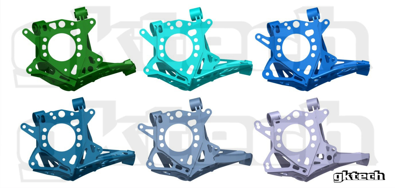
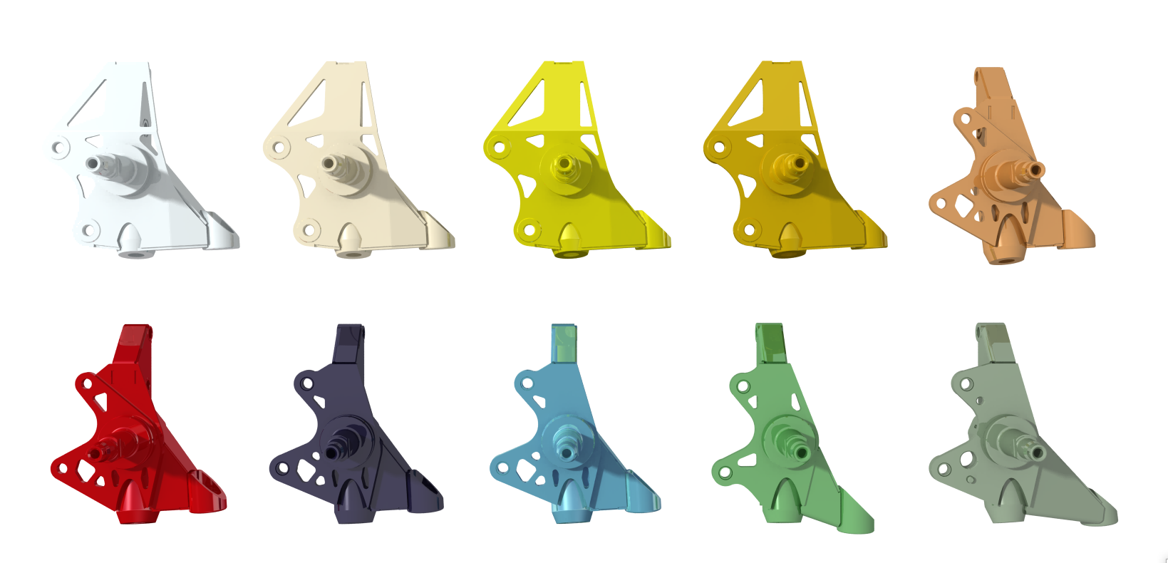
6. COMPONENT DESIGN
It was necessary to divide the body of the new A-arm into pieces for production as a solid single piece arm would have been very expensive to produce. The main body of the arm was divided into 3 different parts that were the rod end adjuster boss, ball joint bearing boss and the body of the a-arm that would be welded together to form a complete A-arm.
There is sufficient clearance between the main body and adjuster housings for welding as one part is rectangular and the other round. The ball joint housing boss required machining of chamfers for welds to have a larger cross-section. The parts are welded in full around the perimeter for maximum strength. The finished arm is electrophoresis coated for durability and aesthetics.
The ball joint bearing housing has been the cause for most of the design updates as some brake system assemblies have had too little rotor clearance from it. The clearance has been improved by lowering the bearing deeper into the housing. The wall thickness has also been reduced but kept within safe margins.
The parts of the a-arm are all CNC machined either on a lathe or a vertical mill.

GKtech products follow Kaizen model to constantly improve products. Updates are made as soon as faults are found or better solutions and designs found. Main reason for updates has been brake disc clearance issue.
- Prototype fitting version with pinch bolt fittings
- Prototype fitting extended version
- Prototype – jam nut adjusters and stacked rear rod end spacers
- First production version
- First update to production version – update brake disc clearance from ball joint bearing housing
- Update strength of the main body and of the lock stop
7. TESTING
Testing was carried out by fitting the extended version arms on the GKTech S14 and going through a few competitive track days. The car was equipped with high grip tyres and 6 piston Wilwood front calipers to assess the durability of the lower arm under heavy braking scenarios as these put the most stress on the curved section of the lower a-arm where the straight tension rod used to be.
Straight design is the best for strength because the forces travel straight between the pivot points, but the lower arm was designed for high tyre clearance and it was not possible to utilize such a basic design. Circuit racing is more suitable testing environment for this product because the forces applied to the front tyres are much less in drifting than in racing. It was also tested in drifting situations on the GKTech R32.

8. SUMMARY
In conclusion, all the design goals were achieved. As with all GKtech products it is a constantly improving product to help keep it on the market for as long as possible and always be on par or surpass the competing products on the market.
The new single piece design has adjustability to out match most two piece designs with the help of stacked spacers and double adjustable QA1 rod ends. This means it is not required to remove the assembled arm from the car for adjustments. Front rod end (tension rod) side spacers need to be re-stacked if adjusting caster, two per side is minimum. Camber can be adjusted through adjusting length of the rear rod end assembly.
Maximum steering angle is adjusted through lock stop distance from the arm itself. It can be adjusted forwards or backwards. The steering angle limiter assembly features serrated washers for more retaining force.
Roll center height can be corrected for using extended ball joint shanks. They come with different height spacers that go between the steering knuckle and the spherical bearing. The high-misalignment type bearing on the wheel side is also from QA1.
All versions of the arms can be extended by 35mm to increase clearance from the chassis or anti-roll bar if used. There are three anti-roll bar end link mounting holes in total. S13 and S14 versions are separated to maximize adjustability as S14 uses longer tension rods in factory specification.