1. INTRODUCTION: S-CHASSIS REAR SUBFRAME COMPARISON
The introduction of the S13 generation S-chassis featured many technical advances over the previous S12 chassis and one of them was the multi-link independent rear suspension. The idea for this newly developed system was to improve cornering stability and available traction. This was achieved with a four link design that consisted of a virtual upper A-arm that was divided into two separate links in order to produce a negative kingpin axis angle. It was done to provide compliance (from the lower A-arm bushings) toe-in effect during cornering, braking and accelerating, thus improving stability and traction.
This suspension system was available with active steering known as HICAS (High Capacity Actively Controlled Steering) where early versions featured hydraulic actuation and later versions used an electric actuator for reduced weight.
The suspension geometry and the design of the suspension member (subframe) received a thorough revision with the introduction of the S14 generation S-chassis.
The purpose of this paper is to find out the differences between S13 and S14 rear subframes to end the myths and assist enthusiasts in finding which versions suits best for them.

Image 1. S13 rear suspension member with aftermarket suspension arms
2. SIMILARITIES
S13 and S14 subframe designs look very similar at first glance, but they are actually very different when examined closely and only a handful of parts can be swapped from one version to the other without modifications. There are however components that can be swapped over from one to the other.
2.1 MOUNTING BUSHINGS
The suspension member bushings are interchangeable between both S13 and S14 versions. There was no change in their physical dimensions.
The OEM parts are a rubber design for low noise and vibration harshness (NVH) and are thus very compliant. The subframe can move around almost 10mm under high lateral loads and worn out bushings can cause clunking noises due to the subframe making contact with other solid components. They are often replaced with solid metal or high durometer polyurethane versions that improve stability and handling at the expense of road noise.
 Image 2. Different rear suspension member bushings
2.2 SUSPENSION UPRIGHT/KNUCKLE
The rear suspension uprights are identical between S13 and S14 with no changes to the suspension geometry or brake system mounting points. Some versions of the rear knuckle feature a removable stud for the coilover mounting, but the location is the same.
There are no differences or updates to it, but the larger washer used for the S14 coilover assembly nut.
There is only a difference in European model S13 where the brake assembly uses a drum-brake for handbrake system and S14 uses a cable operated disc brake system.
 Image 3. S14 rear suspension upright/knuckle
2.3 TRACTION ARM
Front upper links (traction arm) can be swapped between the S13 and S14 rear subframe. It is commonly known as the traction arm because adjusting its length changes anti-squat. Extending the link increases anti-squat value and this can be beneficial with soft rear springs for corner exit traction.
Changing the length of this link also changes bump-steer curve. Making the link longer can remove toe-out characteristics on lowered cars improving grip and handling. OEM length is set to 210mm between the two hole centres.
 Image 4. GKtech rear front upper link (traction arm)
2.4 CAMBER ARM
Rear upper links (camber arm) can be swapped between S13 and S14 rear subframe if there is sufficient clearance from the coilover assembly as S14 coilovers are mounted much higher up in the chassis compared to S13. This means that S14 arms (OEM) mounted to S13 subframe in S13 chassis will likely have clearance issues. Aftermarket arms are commonly designed to be shared between both chassis.
Changing the length has a large impact on the rear wheel camber angle. Rear roll centre height and camber gain are also affected. Extending the arm raises roll center height and reduces camber gain during roll.
 Image 5. GKtech rear upper link (camber arm)
2.5 SWAY BAR
The anti-roll bars can be swapped between both generations as the mounting locations while not the same, are similar enough to allow cross fitment between different generations.
Both S13 and S14 came with a lot of different diameter rear sway bars:
S13:
- EU 200SX S13: 16mm
- US 240SX S13: 21mm (LSD+ABS), 17mm (SE), 15mm
S14
- EU 200SX S14 RHD – 18mm
- EU 200SX S14 LHD – 17.3mm
- US 240SX S14 SE – 15mm
- US 240SX – none equipped
It is important to get correct diameter mounting bushing too when swapping over sway bars. As OEM ones are rather soft it is possible to swap in larger sizes into smaller size versions.

Image 6. S13 rear subframe with sway bar
2.6 CONSTRUCTION
S13 and S14 rear suspension members are both built from stamped mild steel that are welded together. This makes it cheap to manufacture, but susceptible to corrosion. It’s also easy to modify when it is necessary to relocate suspension link mounting positions or mounting new hardware.
Suspension link mounting brackets can benefit from reinforcement plates being welded in for more structural rigidity. This will ensure more consistent wheel alignment under load.
This operation should be done with suspension arm spacers installed in the subframe as it will flex a lot less when re-installing the arms and there have been cases where it is no longer possible to tighten the bolt enough to clamp the arms’ spacers in place. OEM suspension arms or their bushing sleeves can be used for this if aftermarket arms are used. This should not be done with rod ends installed with spacers as the heat from welding will damage the rod end bearings.
 Image 7. S13 rear suspension member with GKtech weld-in brace kit
3. DIFFERENCES
3.1 SUSPENSION GEOMETRY
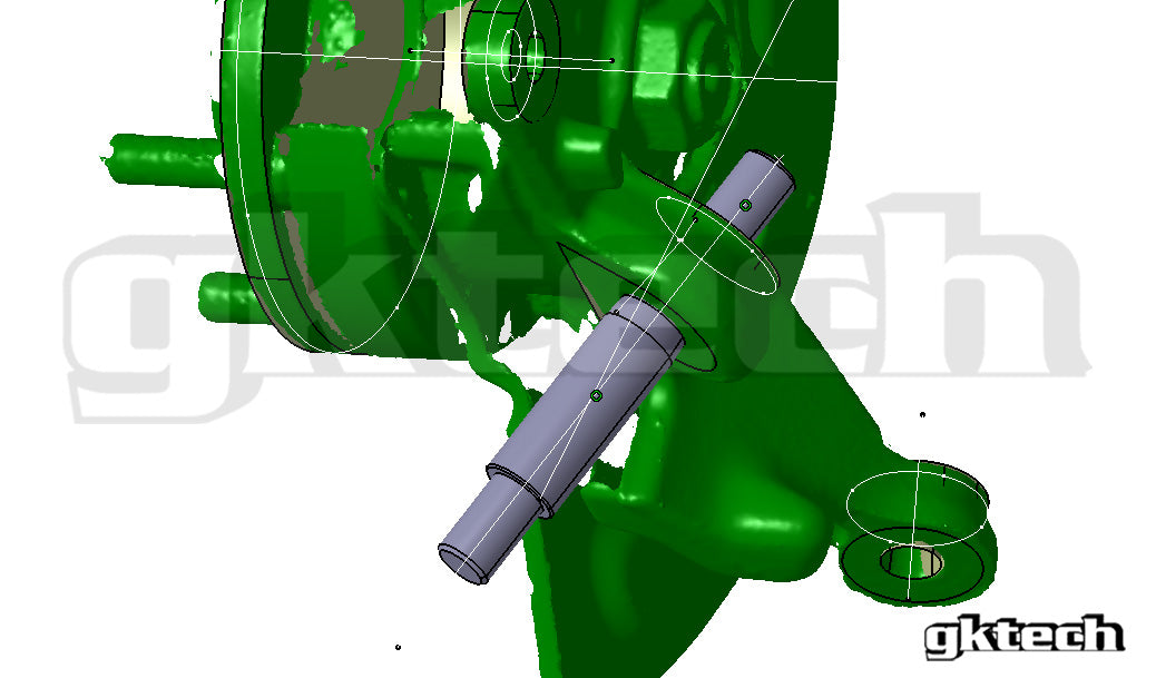
The changes made to the suspension geometry were the biggest change in the S14 rear subframe design over the S13. All of the suspension links mounting points were changed. The largest visually noticeable change is the height of the lower A-arm front pickup point. It was lowered by approximately 50mm to reduce anti-squat. This helps with corner exit traction on bumpy roads as it makes rear suspension more compliant in corner exits.

Image 8. S13(blue) subframe suspension geometry compared to S14 (black)
It must be noted that suspension antis do not change steady state load transfer but only limit suspension travel by changing the amount of load going through the springs. Anti-squat reduces bump travel during forward acceleration from rear wheel torque. S13 has around 45% anti-squat value and S14 is close to 0% in factory trim at the same ride height. As both cars are equipped with the same rate rear springs then the S13 will squat a lot less than S14. This will give S13 a significant advantage in a drag race as it can maintain a flat tyre contact patch due to S14 gaining negative camber as the suspension is compressed.
It is however a different story in circuit racing where more compliant suspension will aid S14 with corner exit traction.
Anti-squat values are also not constants and change throughout the heave of the suspension. S-chassis rear suspension loses roughly 10% of anti-squat with every 10mm of bump travel. A lowered S13 can be in a sweet stop of 20% whereas S14 will be negative meaning the load transferred through the spring and damper increased and the car will squat more as spring has less force to resist it.

Image 9. S13 and S14 rear suspension side view geometry
3.2 LOWER A-ARM (LOWER CONTROL ARM)
The lower A-arm was changed for S14. It features wider spacing for the subframe side mounting. The wider bushings are probably used to allow for more axial compliance under load for increased dynamic toe-in.
The sheet metal stamped body has also been revised. The angle of the outer ball joint has been increased to work with the knuckle from S13 in order to keep the misalignment angle of the ball joint shaft minimal. The mounting for the sway-bar has also been changed to a less deep design as the arm is mounted more parallel to the ground on the S14 subframe.
These parts are not interchangeable between S13 and S14 without modifications to the arm itself as the spacing is too wide for S13. S13 arm can be used on S14 subframe with washers to compensate for increased spacing, but sway bar end link misalignment is an issue if using OEM end links. S13 chassis side bushing spacing is 45mm and S14 is 50mm.
 Image 10. GKtech rear lower A-arm
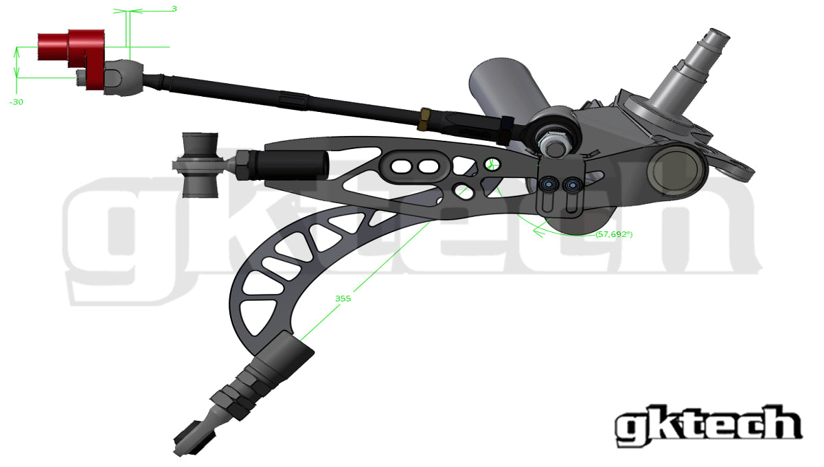
3.3 TOE LINK (TOE ARM)
S13 and S14 toe links both measure 355mm between hole centers, but can only be swapped between the two generations of S-chassis when adding washers to the S13 toe link in S14 subframe. The subframe side spacing for S13 is 40mm and S14 is 50mm. Wheel side spacing is the same
This update matches with lower A-arm spacing width increase and was most likely performed to increase dynamic toe-in under load. Wider bushings allow for less stress in the rubber and steel joint which increases durability.

Image 11. GKtech S14 rear toe link
3.4 CHASSIS MOUNTING SPACING
This part is also a vital step when swapping the subframes between S13 and S14 as conversion bushings are required due to the S14 member using wider chassis mounting stud spacing.

3.5 REAR DIFFERENTIAL HOUSING
The s14 rear subframe was supplied with a bushing mounted differential housing rear cover to reduce noise and vibration transmitted into the cabin. These are distinguishable by S14 having two subframe mounting bolt holes in the rear cover and S13 having four of them.
It was rubber bushing mounted in the front also whereas the S13 was solid fitted to the suspension member. The bushings are soft and can produce wheel hop. They are often replaced with polyurethane or solid metal versions. S14 rear cover also featured ABS sensor mounts as S13 only uses one sensor per rear axle which is mounted in the front of the differential housing.
It is possible to swap differential assemblies between both chassis by using the S13 back cover when installing an S14 housing into an S13 subframe. It is recommended to install solid bushings to the S14 housing when installing into S13 chassis. S13 differential can be used in an S14 with S14 rear cover.
 Image 12. GKtech extended sump S13 differential housing rear cover in grey and S14 in green
3.6 SWAY BAR
It is possible to swap rear suspension sway bars between both chassis but it is worth mentioning that they are spaced differently in the chassis by 21mm on each side with the S14 using narrower mounting bracket spacing.

3.7 NVH WEIGHTS
S13 type rear suspension members are equipped with solid steel blocks welded in close to the chassis mounting stud positions. These serve the purpose of reducing noise and vibrations that hollow construction structures produce. They can be removed to save weight from the car as they are heavy and have little effect when solid or polyurethane mounting bushings are used.

Image 14. S13 rear subframe NVH weights in purple
3.8 EXHAUST HANGERS
S14 subframe exhaust mounting points were also revised as shown in the image below. The front bracket was relocated behind the differential housing cross beam and the rear bracket located more towards the center of the car, most likely for shorter leverage from the exhaust resulting in a stiffer construction that is less prone to fatigue.
The exhaust pipe routing is different in the chassis also so swapping exhausts systems between the two chassis is not a straight forward bolt-on operation.

4. CONCLUSION
In conclusion, the main reasons for S14 rear subframe design updates are ride comfort related. There are more rubber bushings and the lower arm and toe arm ones are longer for more bushing compliancy toe-in action under load.
The S13 rear subframe is better suited for use in drag racing at OEM ride height and can be used in the circuit racing too albeit the ride height must be reduced significantly, but that will cause other problems to occur.
The S14 rear subframe is better suited for use in circuit racing with its low anti-squat, but it is recommended to raise it as close to the chassis as possible for some gain in anti-squat for better traction.

Image 16. S13 subframe 3D scan in grey and S14 in green