1. INTRODUCTION
Steering bind is a negative phenomenon that is common in the world of self-modified steering knuckles for drifting. The steering system is binding when the wheel does not want to steer to lock or return from the maximum steering angle without maximum effort or gets stuck in some cases. It is very dangerous and may cause an accident. The steering system should be checked for binding after modifications have been performed before driving the car at high speed or performing skillful maneuvers.
Binding can also be caused by seized or worn out bearings or other mechanical problems. Geometrical bind will be explained in detail and the Nissan S chassis used as an example.
2. CAUSES
2.1 KNUCKLE GEOMETRY
Modified steering knuckles are often the first reason for binding steering systems if everything else is mechanically sound and close to factory settings.
They usually feature steering geometries where the outer tie rod has been repositioned for more maximum steering angle, but some parameters have been overlooked, most commonly the Ackermann geometry and steering rack distance from the front axle centerline.
Binding can be caused by the steering arm on the knuckle being parallel with the inner and outer tie rod. This means there is no leverage for the steering rack to control the angle of the wheel and as a result the steering wheel becomes excessively heavy near maximum angle. It is a common problem for rear steer rack positions as front steer geometries usually have the rack closer to the axle centerline for geometric reasons such as Ackermann angle at maximum angle since brake discs intervene with optimal placement for street cars.


Figure 2. Included angle for the steering geometry and lever offset

Figure 3. Modified OEM steering knuckle for more steering angle
2.2 OVER LOWERING AND BINDING TIE RODS
Drift cars tend be lowered a lot to achieve lowest possible center of gravity and race car looks and stance, but this always ruins the factory designed steering and suspension geometry.
The cars are then difficult to drive, ride harsh and often bottom out or ride on bump stops.
A serious problem that follows with lowering of the ride height is that the steering system has excessive bump steer and binding of the toe link (inner + outer tie rod).

Figure 4. Overly low S13 with suspension links pointing upwards
2.3 TENSION ROD LENGTH
High positive caster angles are also known to cause bind when adjusted from only the front tension rod (S,R,Z chassis) as the centerline of the axis is moved further away from the centerline of the steering rack. In order to increase positive caster from tension rod, it’s length is reduced. This reduces the included angle of the steering linkage at lock and the steering will bind at lower steering angles.
A 3D model was assembled to help visualize the binding scenario caused by wrong tension rod adjustments if maximum possible steering angle is required. Standard S13 tension rod length of 355 mm was used (measured from rod end ball center to rear bolt hole center).

Image 3. S13 front suspension – straight steering, 355mm tension rod (OEM length)
As the steering approaches maximum steering angle, the steering ratio quickens up and small inputs by the driver result in large wheel angle changes. This is also important to optimize for more consistent and stable drifting.

Image 5. S13 front suspension – steering at bind
Close to over center situation is illustrated in image 5. In this situation the steering rack has no included angle to push the knuckle straight. As the outer tie rod is on same line as the steering arm on the knuckle there is less chance for the knuckle to turn back straight after this point. Also, the load on the tie rod increases exponentially and the components may fail or wear out quickly as a result.

Figure 5. Extended S13 transverse link with removed lock stop bracket
2.5 BENDING TIE RODS
S13 features M12 inner and outer tie rods. They are good enough for street driving, but for drifting with increased steering angle the outer diameter of the M12 inner tie rod is undersized and they may bend and then bind.

Figure 6. Highly misaligned tie rod end
As the factory steering knuckle has the mounting point for the steering knuckle’s outer tie rod pointing in an opposite direction of the toe link, the misalignment is greatly reduced under bump travel (suspension compression).

Figure 7. M12 inner tie rod
3. SOLUTIONS
Since this is a common problem, there are many solutions to it. The write-up starts with the simplest and cheapest mods and step by step level up from simple adjustments to ready-made aftermarket solutions.
3.1 INCREASE TENSION ROD LENGTH
Adjusting tension rod length also changes toe setting. Increasing tension rod length increases toe-in.
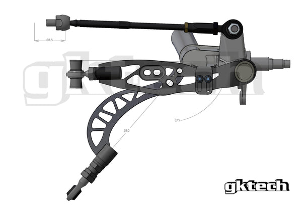
Image 4. S13 front suspension – wheel straight, 5mm extended tension rod
Extending the tension rod by 5 mm gets rid of the binding geometry at displayed rack travel (5,5mm from maximum).
Extending the tension rod cannot be done indefinitely as the wheel well will run out of room and caster settings may become undesirable. Also it will only get rid of bind at the rack travel where it used to bind. It can be used to tune steering ratio but ultimately other solutions provide better results to reduce bind.
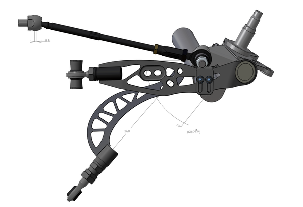
Image 6. S13 front suspension – wheel at lock, 5mm extended tension rod
3.2 LIMITING STEERING ANGLE
If the steering angle is not limited and there is plenty of rack travel to go, the steering wheel will get stuck at lock and not return unless there is a sufficient amount of self-alignment torque acting on the tyre and wheel. During drifting this will make it impossible or very difficult for the driver to save the car from a spin-out.
Steering angle limiters (lock stops) on the lower control arm or knuckle itself are the simple fix if the steering binds at high angles. Limiters can be then adjusted to restrict the maximum steering angle to a point where it will not bind. Many aftermarket lower control arms have such features, including GKtech Budget FLCA and GKtech Single piece FLCA.

Image 7. S13 front suspension, adjusted lock-stop to prevent steering binding
3.3 OFFSET RACK SPACERS – RACK RELOCATION
Offset rack spacers are a simple and cost effective bolt-on solution for high steering angle rear steering rack placement steering systems to reduce bind and reduce steering ratio (slow down steering).
Offset rack spacers bring the inner tie rod’s pivot point closer to axle centerline and as such reduce the Ackermann angle. The reduced steering ratio allows for more precise control of the steering at the limit where 1mm of rack travel can in some cases equate up to 5° of change in steering angle.
The best solution is to physically relocate the steering rack closer to the front axle centerline as this reduces the bending moment created by the offset rack spacer, but this may not always be possible due to competition regulations or technological limitations.
Changing the steering rack offset from axle centerline on fine-tuned bump-steer suspension setups requires re-tuning of bump-steer.
GKtech offset rack spacers move the pivot point 30mm forward and 34mm outwards. They also increase the stroke of the steering rack by 19mm in total (LH and RH side are different, also LHD and RHD and early model S13)

Figure 8. S13 front suspension with offset rack spacer
3.4 RAISING RIDE HEIGHT OR CHANGING ALIGNMENT
Ride height increase is a very easy method of restoring the performance of an overly lowered car. This is recommended when the articulation of the ball joints is maxed out.
It is often overlooked but generally the best approach to budget fixing suspension and steering related problems on a car that has been lowered.
Some extreme cases of wheel alignment also cause steering to bind such as 0° camber on severely lowered car with MacPherson strut suspension. This binding can be reduced by increasing negative camber. Recommended range is -2°…-5°. Excessive negative camber hurts braking performance and increases tyre wear.
Caster range should also be reasonable and recommended range is 4…7°. Excessive positive caster increases bump steer and steering becomes heavy. There is also less tyre contact patch at maximum steering angle.

3.5 AFTERMARKET TIE RODS
Aftermarket outer tie rods can help free up tie rod articulation if the car is lowered as they commonly feature adjustable height for the pivot point via shim stack for bump steer tuning, this also helps with maximum misalignment.
It is recommended to use aftermarket or modified steering knuckles that have the tie rod boss perpendicular to the bearing spindle as tuning bump steer and misalignment will affect Ackermann geometry the least.

Figure 9. S13 front suspension with GKtech outer tie rods
3.6 CORRECTLY MODIFIED STEERING ARM
There are quite a few aftermarket steering knuckles available on the market that have well setup steering geometries with supporting mods such as offset rack spacers, strut tops and lower control arms. As drifters prefer low levels of Ackermann angle but not all agree on how much it is best to find steering knuckles with adjustable outer tie rod position. This allows the end user to find tune the Ackermann geometry to their liking.
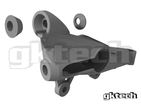
Figure 10. GKtech PROdrift prototype knuckle featuring adjustable Ackermann and increased spindle offset
There are also bolt on solutions to OEM steering knuckles that do away with the problem of tie rod misalignment such as the GKtech roll center kit.

Figure 11. GKtech roll center kit with relocated tie rod for more steering angle and less chance for binding
3.7 READ BEFORE MODIFYING
Car modifications that can be performed or purchased are plentiful, but not all of them are well thought and engineered solutions. Some of them also require professional installation and setup.
Experimenting with different product is a risk car owners take. We recommend using parts from the same manufacturers as already used on the car that alter the steering geometry. It is rarely a good idea to mix and match parts between different brands as they usually are designed only to work with their own products and do not work with all other options available to buy. All modifications done and parts replaced should be tested in a safe environment and do not be afraid to ask for more information from the products’ manufacturers.
Wheel alignment and ride height settings should not be exaggerated if maximum performance is required.
Author: Siim Õisma
Bsc Automotive engineering, Msc (in training) Product development
GKtech engineer since 2013
